Geometry Generation
Introduction
OpenVSP is a parametric aircraft geometry tool. It allows the user to quickly generate aircraft geometries. We will use it to generate the ONERA M6 wing. This is not a full blown tutorial, more a walk through. If you want to learn more about it, you can go to their tutorial videos
Files
Navigate to the directory overset/geo in your tutorial folder. Copy the file profile_m6.dat from the
tutorial directory:
cp ../../../tutorial/overset/geo/profile_m6.dat .
Geometry Overview
Before we start, we should familiarize ourself with the geometry we are going to create. The real ONERA M6 experiment looked like this [O1]:

ONERA M6 experiment.
As we are not the first to simulate this wing, we can grab the geometry data and the airfoil from [O2]. Here is a short summary:
Airfoil |
profile_M6 (this can also be found in the tutorial folder) |
Root Chord |
0.8105 m |
Tip chord |
0.4559 m |
Semispan |
1.1963 m |
Leading Edge Sweep |
30° |
Geometry Generation
OpenVSP Window
If you open OpenVSP the first time, it should look like that:
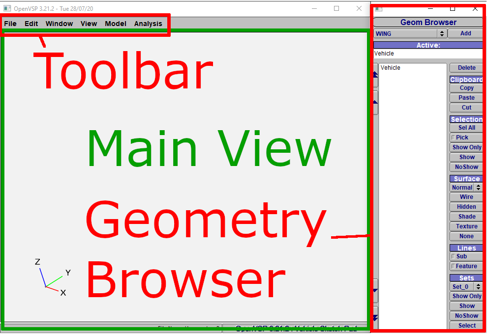
OpenVSP Overview.
Lets start the geometry generation:
Add a new Wing
Choose
WINGClick
AddA new Window
Wing: WingGeompops up
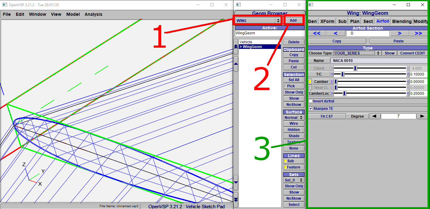
Add a new wing to OpenVSP.
We notice a new geometry in the Main View. This is the wing we just added. It also
shows up as WingGeom in the Geom Browser. To control the view, use
the following key- and mouse combinations:
- zoom
Press the middle mouse button and move your mouse up and down.
- rotate
Press the left mouse button and move your mouse.
- move
Press the right mouse button and move you mouse.
Manipulate the wing geometry
Move your view, so you can take a look the whole wing. The first thing we notice, it is a ‘full’ wing, but we need only half of it. To change this, do the following:
Click on
XFormUncheck
XZin theSymmetryarea
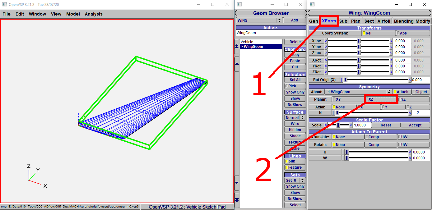
Disable XZ Symmetry.
Now we change the wing geometry. OpenVSP has no units, but we want to create the mesh in meters and thus choose our unit size to be one meter.
Click on
SectChange the values to the values listed in the table above
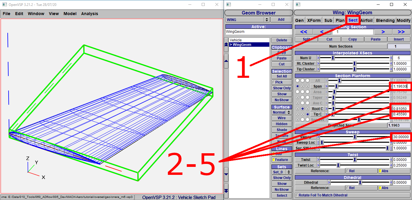
Adjust the wing geometry.
To make the meshing process easier, we will round the tip:
Click on
PlanChoose
Roundfor theTip Cap Type
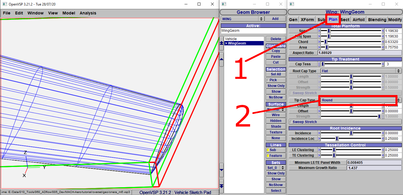
Adjust the wing geometry.
Change the airfoil
Now, the wing geometry is as it should be, but we still have to change the airfoil:
Click on
AirfoilSelect
AF_FILEforChoose TypeOpen the file
profile_m6.datin thetutorial\overset\geofolderClick on the
right single arrowto select the Tip airfoilrepeat the process from
2to3
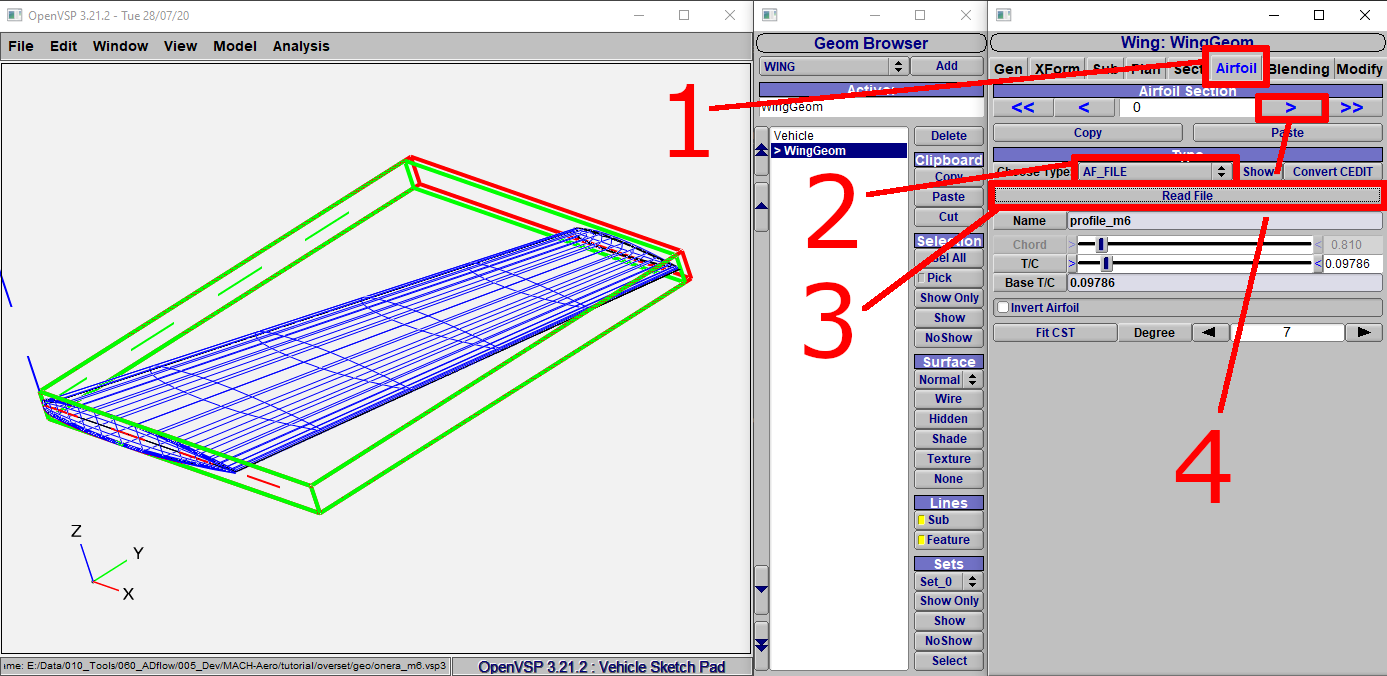
Change the airfoil.
Export the geometry
Now we can export the geometry to read it into our meshing software. It might also be a good idea to save it first.
Click on
File->ExportClick
Untrimmed IGES (.igs)Choose the proper unit. In this case it should be meter
Click
OKand save it
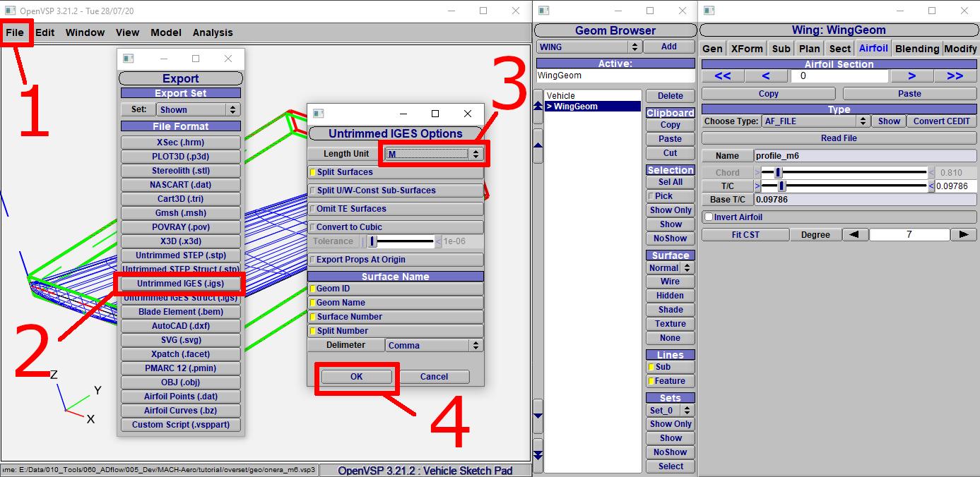
Export the geometry.