Surface Meshing with ICEM
Warning
This page assumes you are using ICEM for surface meshing. For a version of this page that uses Pointwise see here.
Introduction
Now that we have a geometry definition, we can start meshing it. Our end goal is to generate a structured volume mesh around the geometry that can be used by ADflow. Unlike the airfoil, this is a two step process for 3D geometries.
We generate a surface mesh, a structured grid of points on the B-spline surfaces defining the geometry that create a watertight surface.
We extrude that surface mesh, using a hyperbolic or elliptic mesh extrusion algorithm, into a volume mesh that we can use with ADflow.
This page describes how to accomplish the first step using ICEM as the meshing tool of choice. ICEM CFD is a meshing software with advanced CAD/geometry readers and repairs tools. It allows the user to produce volume or surface meshes. At times ICEM may test your patience, however, it offers a lot of functionality and is quite handy once you get to know its quirks. A full ICEM CFD tutorial can be found here. For more theoretical background of mesh generation, refer to “Thompson, et.al. Handbook of grid generation. CRC press, 1998.” In this step we will focus on generating the L1 surface mesh. Generating the remaining members of the mesh family will be covered in the next step.
Warning
Make sure you save your work often when using ICEM. It is known to crash at the worst possible moments. We also recommend saving instances of a single project in different locations just in case you need to go back to a previous state.
Files
Navigate to the directory wing/meshing/surface in your tutorial folder.
Basic ICEM Usage
This section contains some general usage information that will helpful in becoming familiar with ICEM. The actual tutorial starts with Creating a surface mesh.
Opening ICEM
First, determine where the ICEM executable is located.
which icemcfd
The output should look like the following, where <your-version> is the version you installed.
/usr/ansys_inc/<your-version>/icemcfd/linux64_amd/bin/icemcfd
Then run the executable with superuser privileges, replacing the path with the results of the previous command.
sudo /usr/ansys_inc/<your-version>/icemcfd/linux64_amd/bin/icemcfd
File Types
ICEM uses several native file types with the following extensions:
- .prj
Project file. Contains references to the geometry and blocking files of the same name.
- .tin
Geometry file. Contains a geometry definition made up of points, lines, and surfaces.
- .blk
Blocking file. Contains the definition of the geometry and parameters used to generate the mesh.
Changing the appearance of the geometry
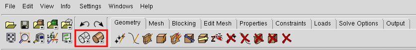
The two buttons outlined in red can be used to view the geometry as a wire frame (left button) or a collection of opaque surfaces (right button).
Creating a surface mesh
Load the geometry
In ICEM, select File → Geometry → Open Geometry.
Navigate to the geometry folder and open wing.tin.
ICEM will prompt you to create a project called wing.prj. Select Yes.
Rename Parts
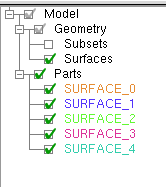
You will see in the model tree that there are 5 different parts with arbitrary names. We want to redefine a single part that contains all wing geometry and call it WING.
Right-click on Parts in the model tree and select Create Part.
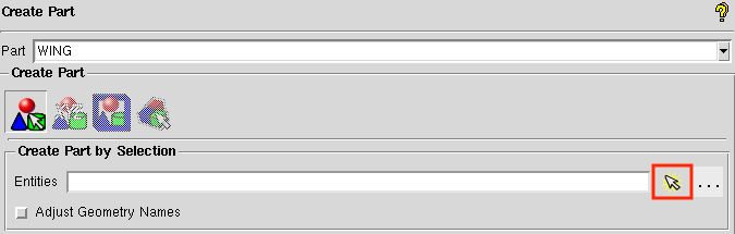
The options for creating a new part will appear in the lower left-hand pane as shown below.
Change the name from “PART.1” to “WING”.
We want to create the “WING” part by selecting objects in the viewing pane.
To do this, select the arrow to the right of the Entities box (outlined in red) and then drag a box (with the left mouse button) over all the wing surfaces in the viewing pane.
All of the selected geometry should become highlighted.
Now click the center mouse button to verify the operation.
All of the selected components should become the same color, and a new part called “WING” should appear in the model tree under Parts.
To refresh the model tree, deselect and then reselect the checkbox next to the “WING” part.
This should make all of the other parts go away.
Auxiliary Geometry
Before actually creating the mesh, it is helpful to create some additional geometric features to use as references for the mesh.
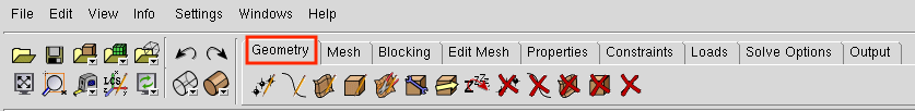
All geometry creation and manipulation is done under the Geometry tab, outlined in red in the image below.
1. Create curves and points from surfaces
You will notice that the geometry section of the model tree contains only Subsets and Surfaces. We want to see the curves and points that define the boundaries of these surfaces. This can be done by clicking on the
Repair Geometrybutton in theGeometrytab.The
Repair Geometrysection will open up in the lower left pane. The default operation in this section isBuild Diagnostic Topology. This will create the curves and points that define the surface intersections, if they are missing. ClickApplyat the bottom of the pane (the default options should be sufficient). You will see red and yellow curves appear on the geometry. The red curves denote an intersection between two surfaces and the yellow curves denote unattached surface edges. Additionally, points appear at the corners of the surfaces. If you look at the model tree now, you should see Subsets, Points, Curves, and Surfaces under the Geometry branch and a single part named “WING” in the Parts branch.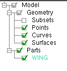
There are some curves and points missing still. If you look closely at the trailing edge of the wing, you will see that only one curve was made when we repaired the geometry (uncheck the
Surfacesbranch in the model tree underGeometryto make it easier to see). This is because the lower surface of the wing is continuous with the trailing edge surface, so there is no intersection. We need to make a curve to define the lower edge of the trailing edge. First we need to create some points. To do this, let’s go to theCreate Pointbutton of theGeometrytab and then selectCurve Endsin the lower left pane.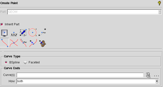
Select “both” in the
Howdrop-down menu and then click the arrow to the right of theCurve(s)box. Now select the curve on the upper edge of the trailing edge and the lower surface curves at the root and tip of the wing. Now let’s go to theCreate/Modify Curvebutton of theGeometrytab.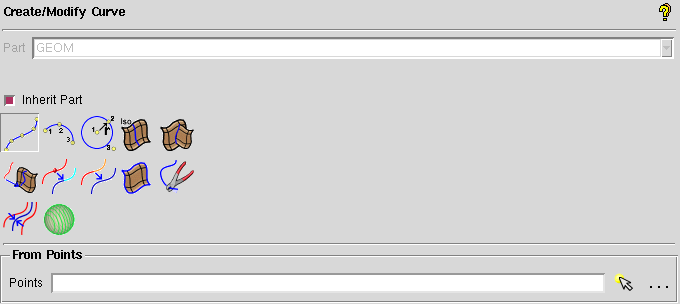
Select the first option in the lower left pane (
From Points). This will create a straight line between two points or a spline between multiple points. Select the arrow to the right of thePointsbox and then choose the points at either end of the lower edge of the trailing edge. For good measure, you can close off the trailing edge by creating curves between the upper and lower surfaces at the root and tip of the trailing edge. In the end, your trailing edge should look like this (onlyCurvesandPointsare turned on in the Geometry tree).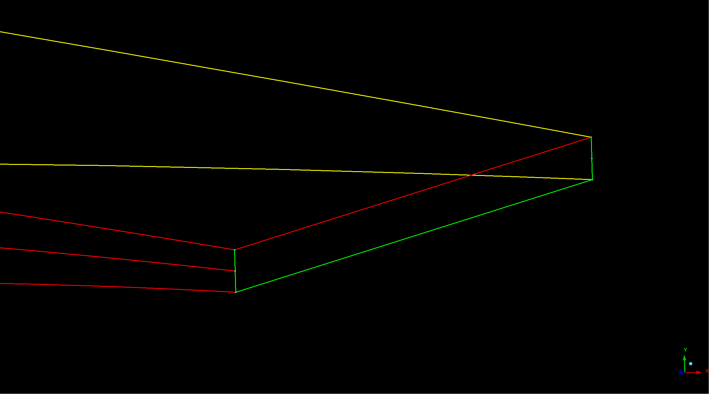
1. Create auxiliary curves
Now let’s create some curves to help define the leading edge section of the surface mesh. First we need to create some points, so go back to the
Create Pointsection. This time select theParameter along a Curveoperation.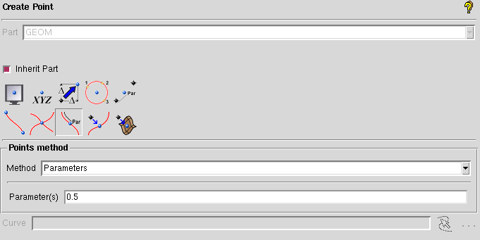
Put 0.01 in the
Parametersbox and then click the arrow to the right of theCurvebox. Now select the upper and lower airfoil curves at the wingtip. You should see two points appear near the leading edge. For the root airfoil section, the curves are flipped, so we need to enter 0.99 in theParametersbox and then select the upper and lower curves just like we did for the wingtip.Now we need to connect these points with curves. Go back to the
Create/Modify Curvebutton under theGeometrytab and select theFrom Pointsoperation. Connect the points on the upper surface with one line and the points on the lower surface with another line. Now the leading edge of your wing should look like this: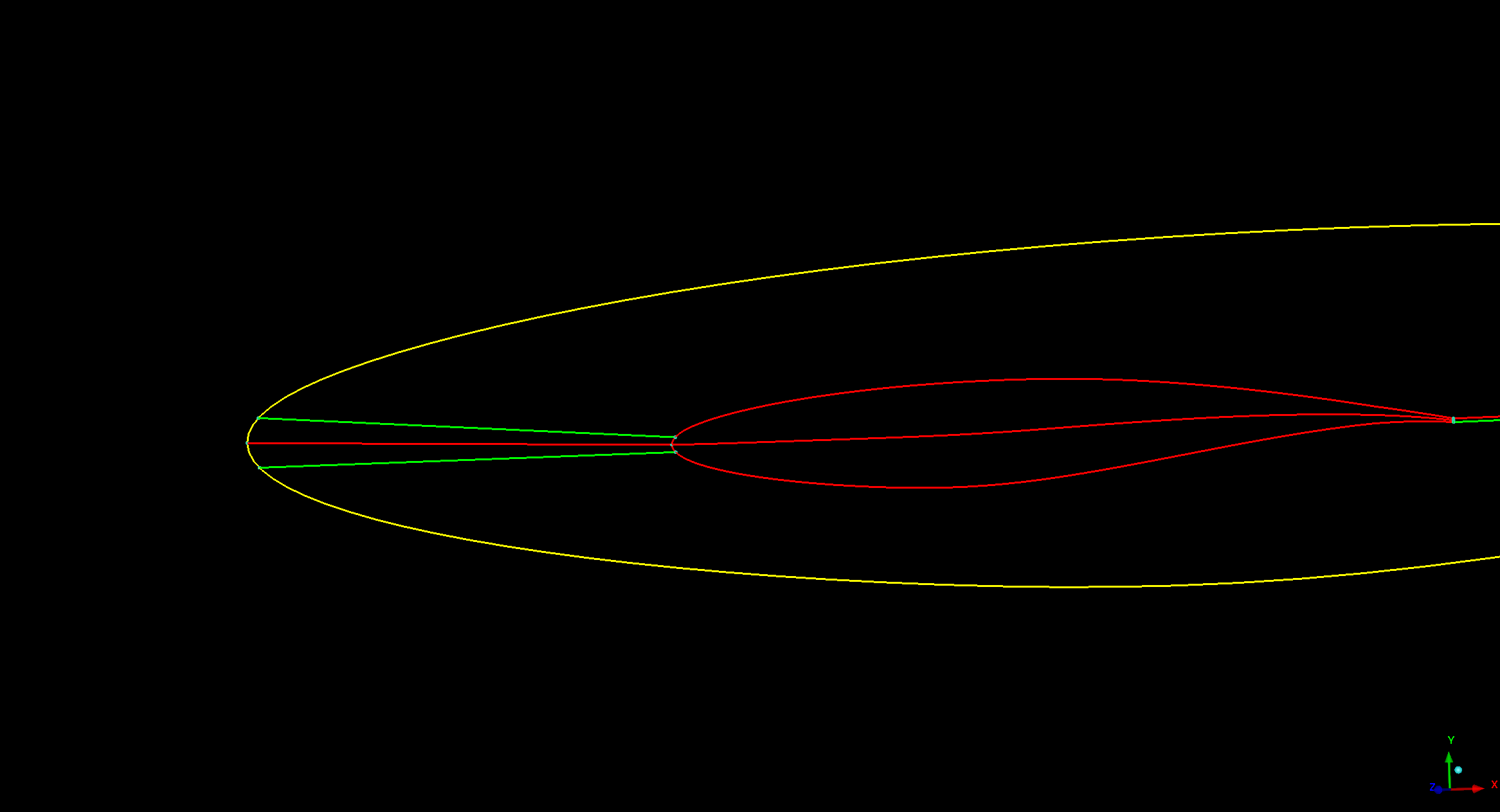
Blocking
The blocking is the underlying structure that defines the mesh. In the blocking we can define how many cells we want and how we want them to be arranged. For this case, we will define properties for the edges of the blocks which will then be project by ICEM onto the geometry to create a surface mesh.
1. Create 3D blocking with bounding box
The best way to create the blocking is to first create a 3-D bounding box and to then convert that blocking from 3-D to 2-D. This approach is preferred as it helps ICEM understand the topology, often preventing future issues.
To do this, under the
Blockingtab, select the first icon,Create Blockshown here: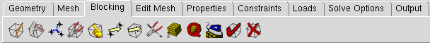
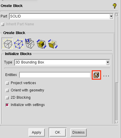
This opens a menu in the lower left corner of the window. With the default options, click the button next to the input box for the entities (if it was not automatically selected). This button allows you to select the entities you want to create a blocking for from the CAD model. Directions for selecting entities are found in red text at the bottom of the CAD window. To create a bounding box around the entire wing, select all of the wing entities by clicking and dragging with the left mouse button.
2. Convert 3D blocking to 2D blocking
Now the 3-D bounding box needs to be converted to a 2-D blocking (as we only want a surface mesh output from ICEM). To do this, select the fifth icon in the
Create Blockmenu (shown below).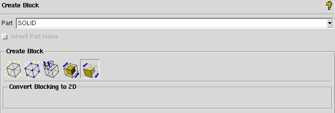
After selecting the fifth icon, select OK or Apply at the bottom of the Create Block menu. If the conversion was successful, in the dialog box there will be a message reading “…Blocking successfully converted to 2D…”
Look back at the model tree and you should see something like this (expand the Blocking tab).
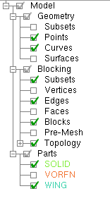
If you check the box next to
Blocks, you will see green surfaces appear surrounding the wing. Since the wing root is on the symmetry plane, we want to remove the block along the symmetry plane. This can be done with theDelete Blockbutton in theBlockingtab. Check the box for “Delete permanently” and then select the green surface parallel with the root airfoil. It should become highlighted like in the image below.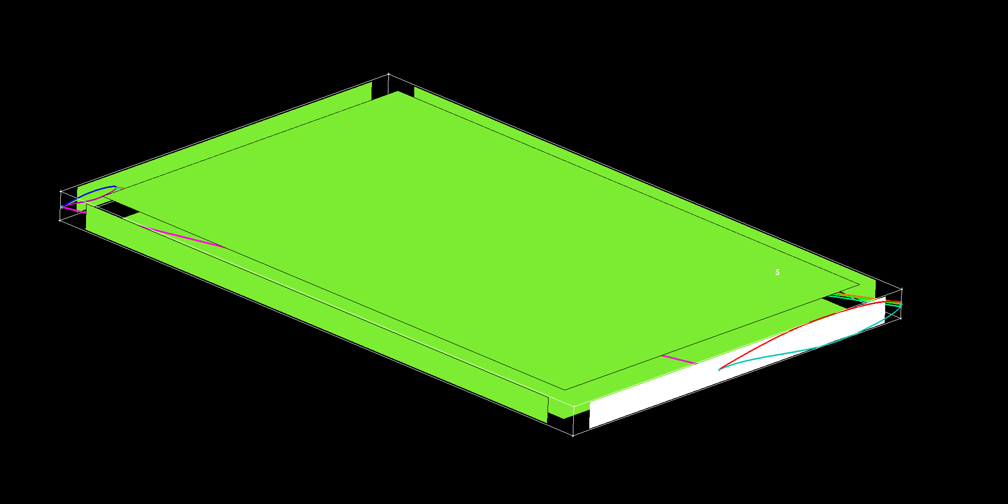
To complete the operation, click the middle mouse button.
3. Associate blocking to geometry
In order to control the shape of the surface mesh, we can associate the block edges to curves on the geometry. We can do this with the
Associatebutton in theBlockingtab. First, let’s associate the vertices of the blocks to points on the geometry.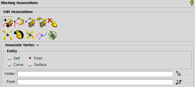
The first operation in the
Associatepane allows us to associate vertices to points, curves, or surfaces. We want to associate the 8 vertices to the corresponding 8 points at the corners of our wing. Click the arrow to the right of theVertexbox. The first selection in the view pane will choose the vertex and the second selection will choose the point to which it will be associated. The association will happen immediately and the vertex should move to the same location as the point. You can continue selecting vertex and point pairs until you are done. After associating the vertices at the wing root, the blocking should look like this.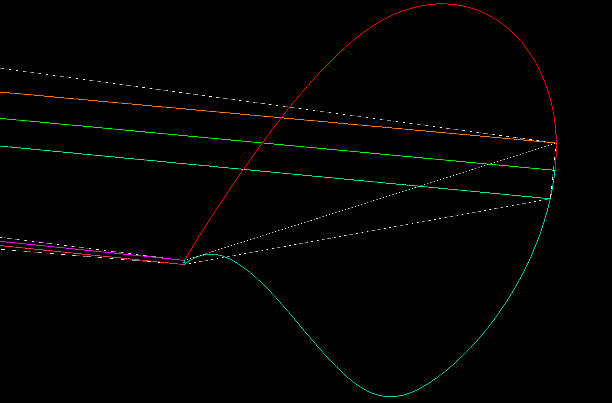
Now do the same thing at the wing tip.
The next step is to associate the block edges to the geometry. Go to the second button in the
Associatepane:Associate Edge to Curve. Now select the upper edge at the symmetry plane and then select the upper curve of the root airfoil. You must confirm each selection by clicking the middle mouse button. After the edge is associated, it should turn green. Do the same thing with the lower edge and the lower curve of the root airfoil. For the vertical edge at the leading edge of the root, we need to associate to both the upper and lower root airfoil curves. First select the edge and confirm, and then select both airfoil curves and confirm. Do the same for the wingtip.Let’s check out the state of the mesh at this point. We can view the mesh by checking the box next to
Pre-Meshin theGeometrybranch of the model tree. If you are in wire mesh view, switch to a solid surface view (see Changing the appearance of the geometry). You will see that the mesh is collapsed in on itself (don’t worry, we’ll fix it in the next step).
4. Split and adjust edges
To remedy the collapsed mesh, we need to create some control points along the edges.
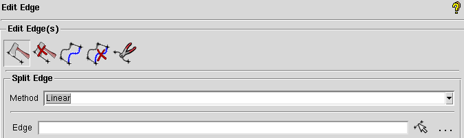
Go to the
Edit Edgebutton in theBlockingtab. Under theSplit Edgeoperation, choose the “Linear” method. Then click the arrow to the right of theEdgebox and select the upper horizontal edge at the symmetry plane. Immediately, a point will snap to the associated curve (make sure you drag it up to the upper curve of the airfoil before you let go). Once you let go of the mouse button, a dialog box will pop up with the following message: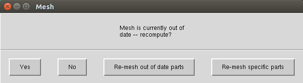
Select “Yes” and you will see the mesh snap up to the upper surface. Do the same for the wingtip.
At this point we will have a very coarse discretization of the wing surface that looks like the following at the wingtip.
Un-check
Pre-Meshin the model tree to avoid the recompute mesh dialog box popping up at each step.
5. Define edge properties
To further refine the mesh, we need to modify some edge parameters. In the
Blockingtab, click on thePre-Mesh Paramsbutton (a cube with a grid). In the menu in the lower left corner, click on theEdge Paramsbutton underMeshing Parameters. For theEdge, select the vertical edge at the leading edge of the wingtip. Then type in 17 (in general this should be an odd number, 4n+1 where n is an integer so that multi-grid options can be used) forNodes, selectUniformfor theMesh law, selectCopy Parameters(with the defaultTo All Parallel EdgesunderCopy), and clickOK.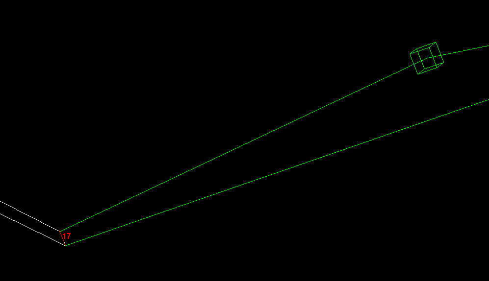
Note
The most commonly useful mesh-spacing laws are
BiGeometric,Poisson, andHyperbolic. When specifying edge spacings, it is important to keep in mind that there should not be large jumps in cell sizes across edge boundaries. Large changes in cell size can result in pyHyp errors and poor quality results.Now we will specify parameters for the edges associated with the upper and lower airfoil curves at the wingtip. Select the upper edge at the wingtip for
Edgein thePre-Mesh Paramsmenu. Specify 161 forNodesand selectHyperbolicfor theMesh law. Next, to avoid large discontinuities in element size, we will select some edges to link to this edge. This is done by specifying edges to link toSp1andSp2. The edge will have an arrow displayed on it. This arrow points from the vertex corresponding toSp1to the vertex corresponding toSp2. Click on the box to the left ofSp1and then click onSelectand select the vertical edge at the leading side of the wingtip (or the trailing edge ifSp1corresponds to the trailing edge). Then do the same forSp2with the vertical edge at the trailing side of the wingtip. Click the box forCopy Parametersif it isn’t selected by default (this will copy these settings for the three other edges at the wingtip and the root) and clickOK.Next, we will set the edge parameters for the edges running spanwise along the leading and trailing edges of the wing. Select the upper edge at the leading edge of the wing for
Edgein thePre-Mesh Paramsmenu. Specify 161 forNodesand selectUniformfor theMesh law. The click on the box to the left ofCopy Parametersand selectTo All Parallel EdgesunderCopy(if not already selected by default). At this point the pre-mesh should look like the following at the wingtip.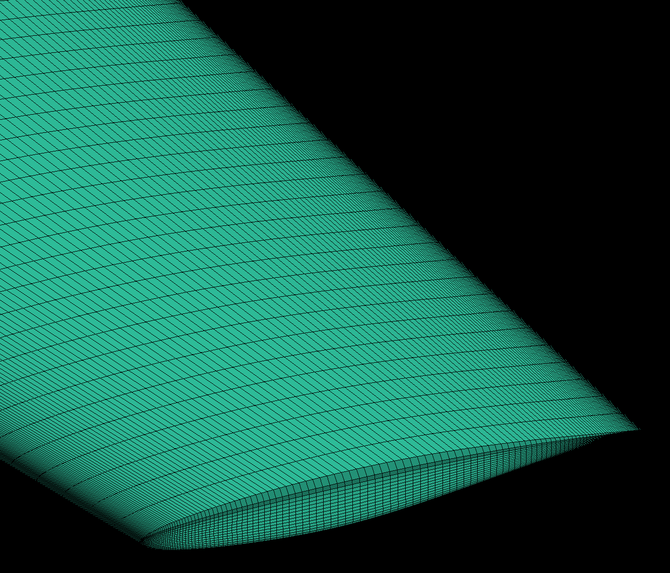
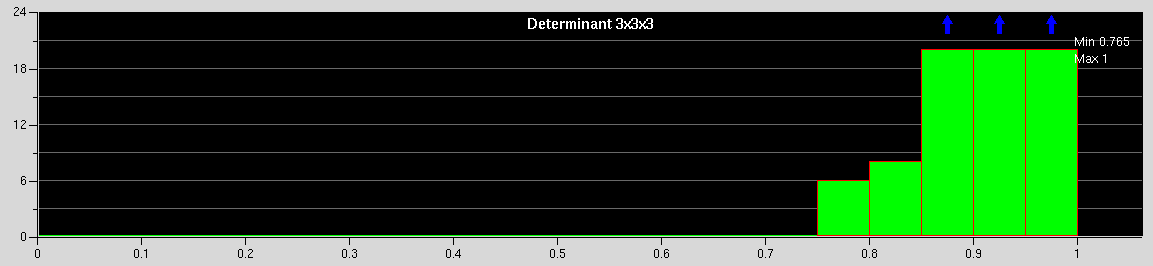
7. Check mesh quality
We can see that the above mesh is far from ideal (for example, due to the large changes in element size at the wingtip). We can also use the
Pre-Mesh Quality Histogramtool to check the mesh quality. In theBlockingtab, click on thePre-Mesh Quality Histogrambutton (a red Q around a cube with a grid) and then click onOKwith the default settings. The following histogram should appear on the bottom right of the window.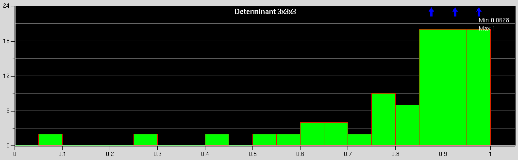
This shows that we have a few poor quality elements (less than 0.5). To see the elements corresponding to a particular bar of the histogram, click on the bar. Hiding the pre-mesh and then pressing
xon the keyboard should show the elements. Showing the pre-mesh again should help see where they lie with respect to the wing. These happen to be at the leading edge of the wingtip. Also, we need to improve the quality of the mesh as the elements transition from the upper and lower surfaces of the wing to the wingtip surface.For surface meshes that will be used in pyHyp, the minimum quality of any cell in the mesh should be about 0.7. The mesh needs to be adjusted if there are low quality cells. Oftentimes, adjusting node spacing or some associations can fix low mesh quality issues. However, adjusting the mesh to assure high quality can often be a bit tricky, particularly for inexperienced users.
Taking a break at this point and reviewing the steps so far is recommended.
8. Improve mesh
To improve the mesh, we will first split the block to gain a little more flexibility with the mesh. In the
Blockingtab, click on theSplit Blockbutton (an axe with a cube). In the menu at the bottom left, also select theSplit Blockoption (an axe with a cube). Click on the arrow to the right of theEdgebox, then click on the upper leading edge near the wing tip, as shown below to split the block.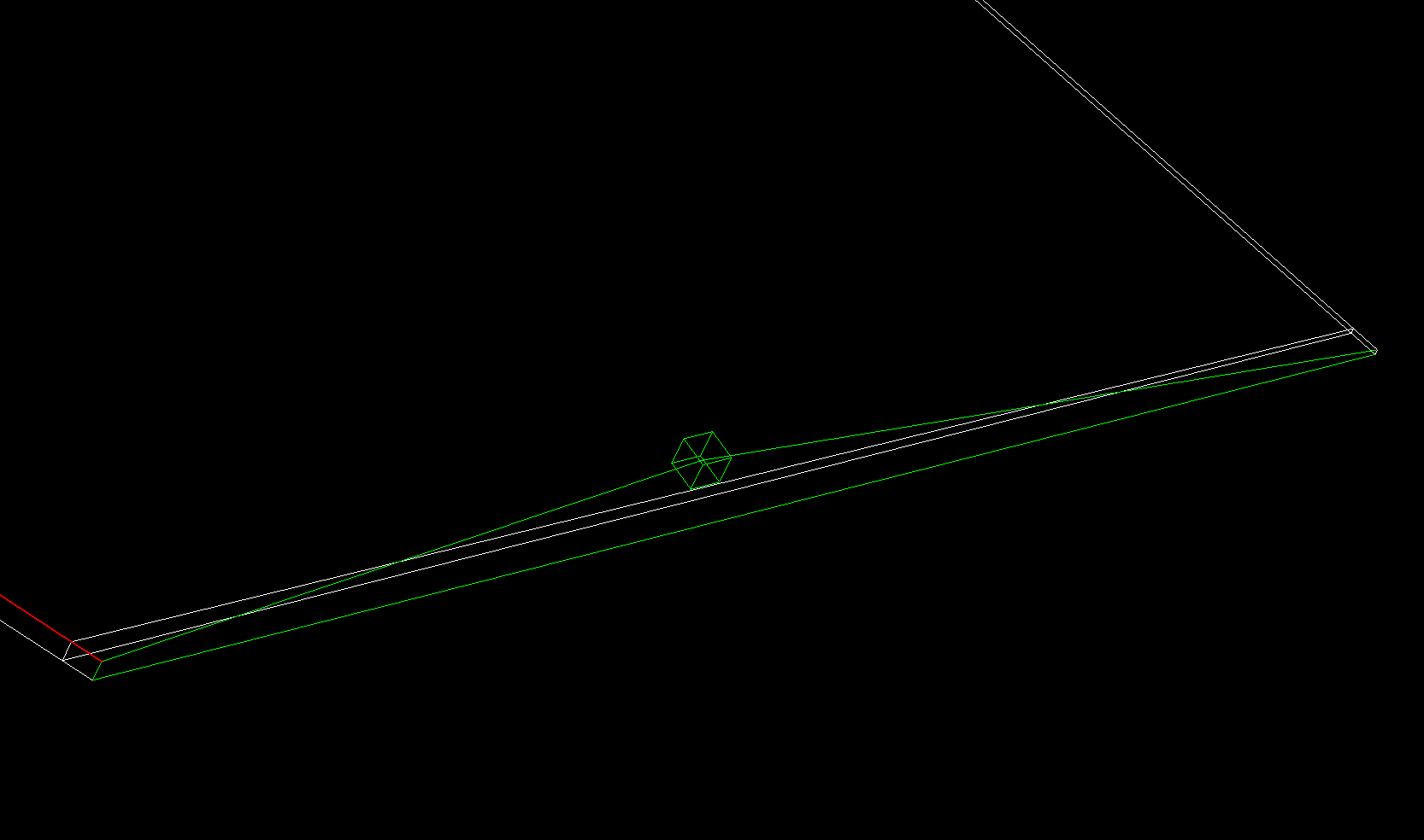
After this, we will first change the edge parameters of the new horizontal edge at the leading side of the wing. Go to the
Edge Paramsmenu underPre-mesh Paramsas shown earlier. Select the edge, enter 17 forNodes, selectGeometric2for theMesh law, linkSp2to the vertical edge at the wingtip, click the box forCopy Parametersif it is not already selected by default, and accept the options.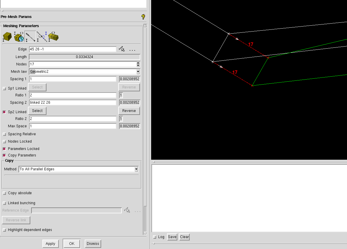
Note
For reference, in the menu shown above, the numbers in the gray boxes next to some items (e.g.,
Spacing 1andSpacing 2) show the smallest values that can actually be achieved. Also, thelinkednumbers shown when linking edges (e.g.,linked 22 26) correspond to the numbers of the vertices of the edges. These numbers can be displayed by checkingVerticesin the model tree and then right-clicking it and clicking onNumbers. These numbers can be used to verify that the correct edges are selected while linking.Similarly, we will now set the
Edge Paramsfor the longer horizontal leading and trailing edges. Select the top edge at the leading side, enter 161 forNodes, selectHyperbolicfor theMesh law, setSpacing 1to 0.1, linkSp2to the horizontal edge closer to the wingtip that we set parameters for right before this, click the box forCopy Parametersif it is not already selected by default, and accept the options. At this point the mesh should look something like the following at the wingtip.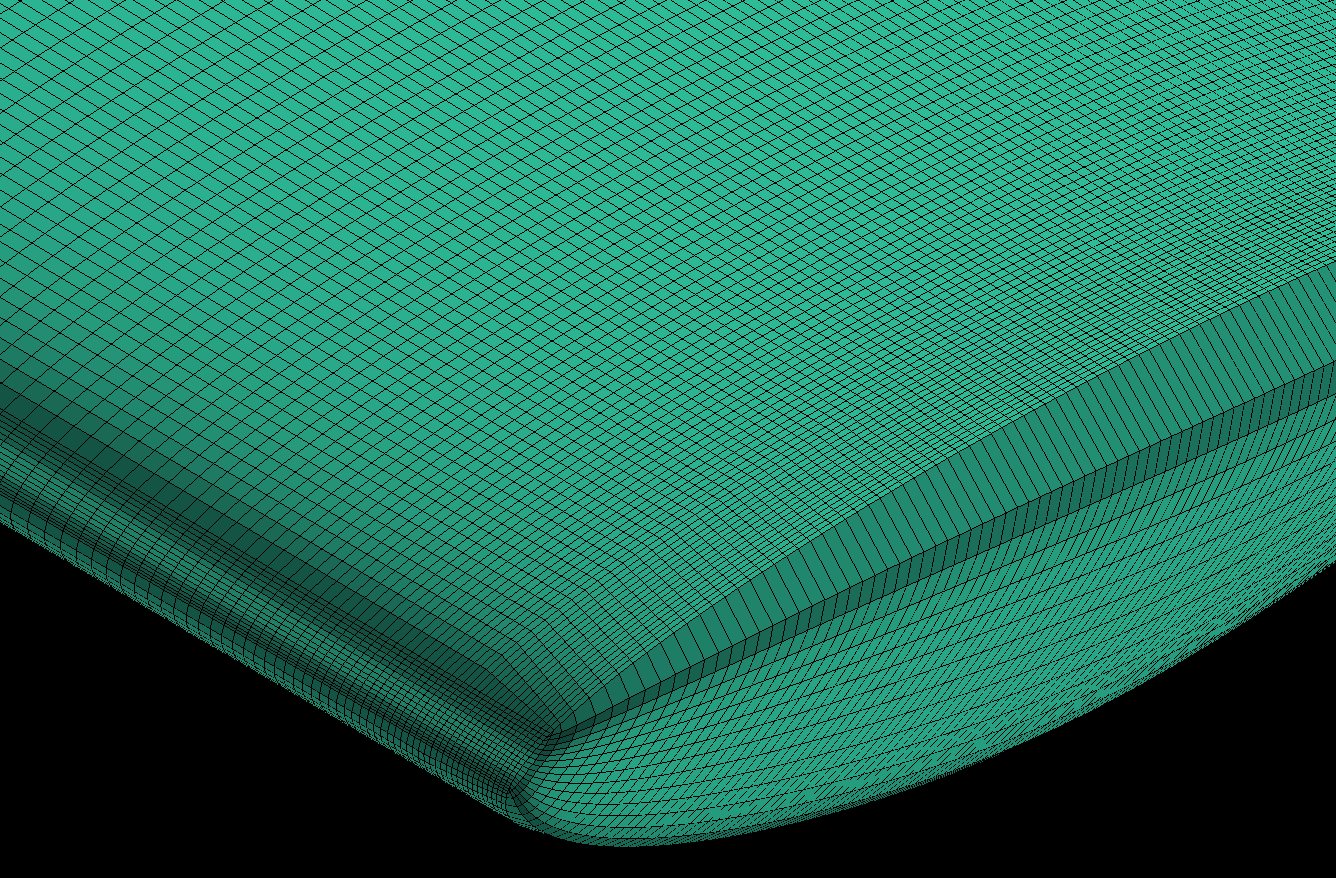
Next, we will disassociate the edges at the wingtip from the curves we had selected in Step 3. In the
Blockingtab, click on theAssociatebutton, and click theDisassociate from Geometry(a finger with an X) button in the bottom left menu. ForEdges, select both halves of the top edge at the wingtip and the bottom edge at the wingtip, and accept.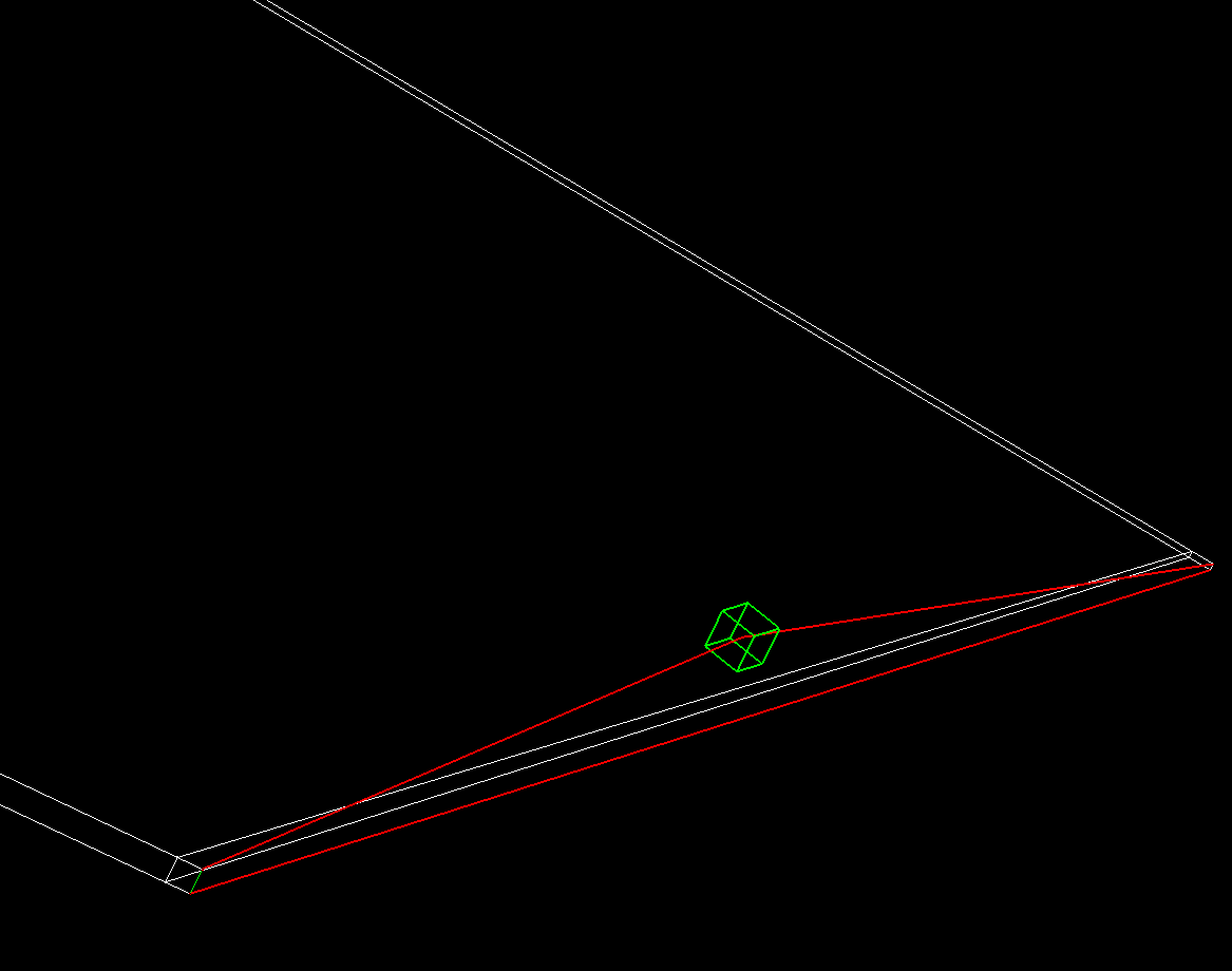
Next, click the
Associate edge to Surfacebutton underEdit Associationsthen select both halves of the top edge at the wingtip and the bottom edge at the wingtip, and accept.Now we will split these edges into a lot more pieces (
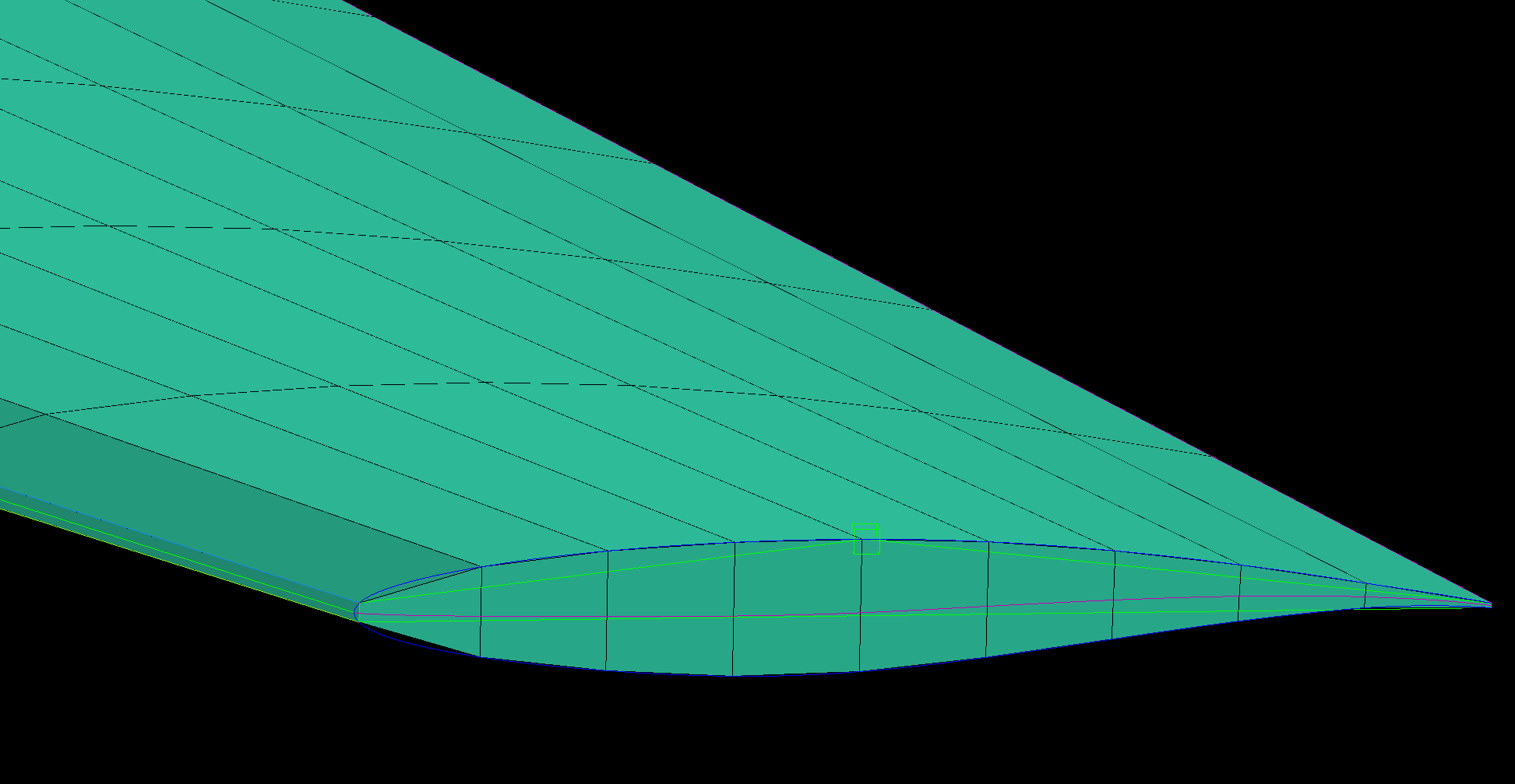
Edit Edgein theBlockingtab, thenSplit Edgeas described in Step 4). Split the top edge at the wingtip into about 6 segments and split the bottom edge at the wingtip into about 12 segments. For the upper chordwise edge inboard of the wingtip edge, split the edges into 2 segments. Splitting edges provides greater flexibility and more can be created if required. The following is what the edges should look like at this point.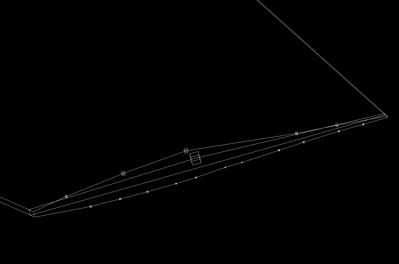
The next phase will be more challenging because these edges are now associated with surfaces and moving the vertices can be tricky. In the
Blockingtab, click on theMove Vertexbutton (an arrow with two vertices). WithMove Vertexselected in the bottom left menu, click on the button to the right ofVertexand adjust the vertices of the upper and lower wingtip edges to look like the following image. MakingSurfacesvisible (as a wireframe) from the model tree should also help. This process will require some patience. Rotating the view should show if the vertices actually moved to the desired location. Also, theFix X/Y/Zoptions in the menu can be useful to prevent the vertices from moving in unwanted directions while dragging them.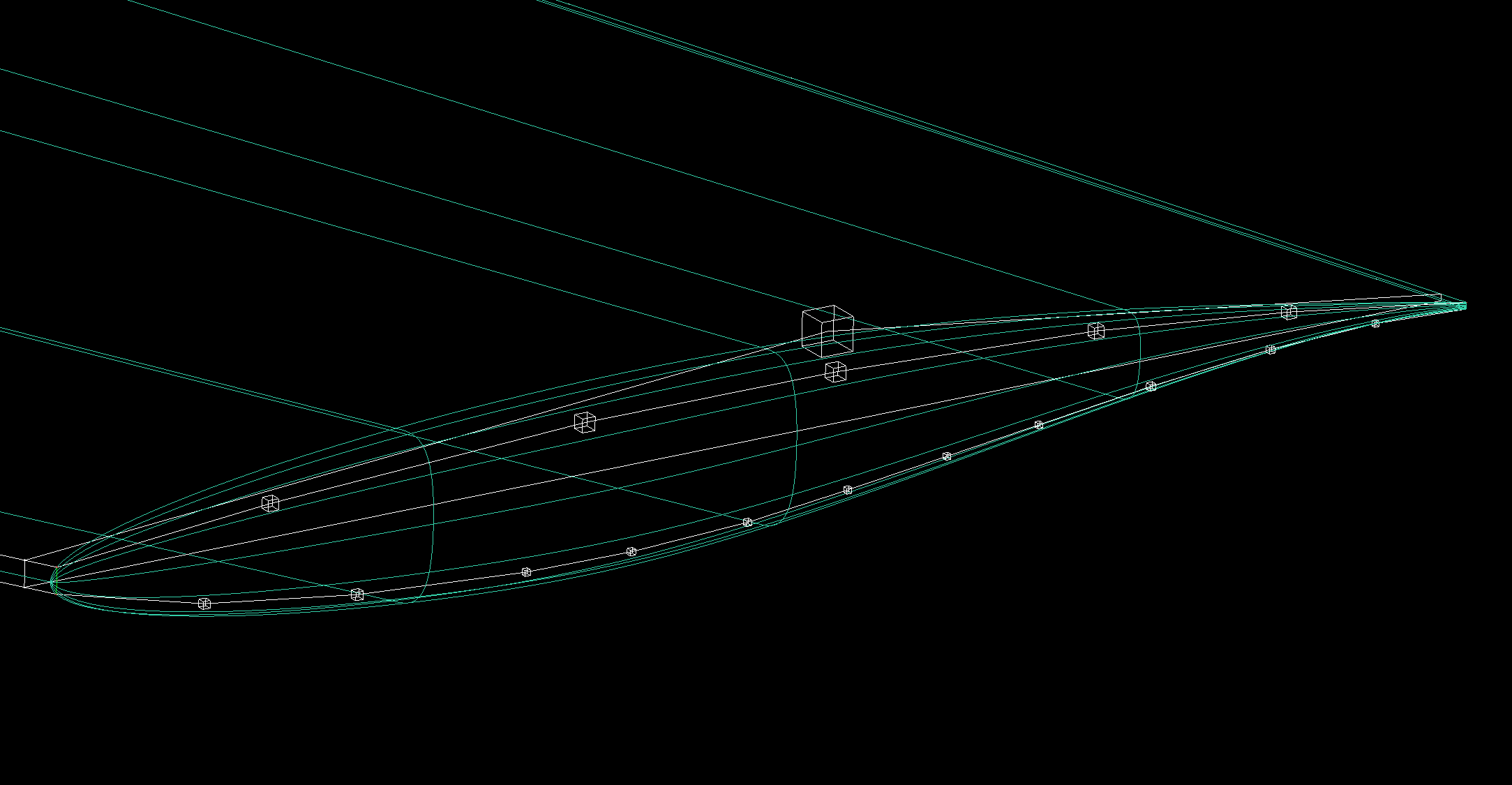
The pre-mesh should look something like the following at this point.
If you see an overlapping or collapsed mesh, check the associations of the edges. Right click on
Edgesin the model tree and click onShow Association. If an edge associated with a surface does not have an arrow pointing toward the surface, splitting and dragging should fix the problem as shown earlier in Step 4.
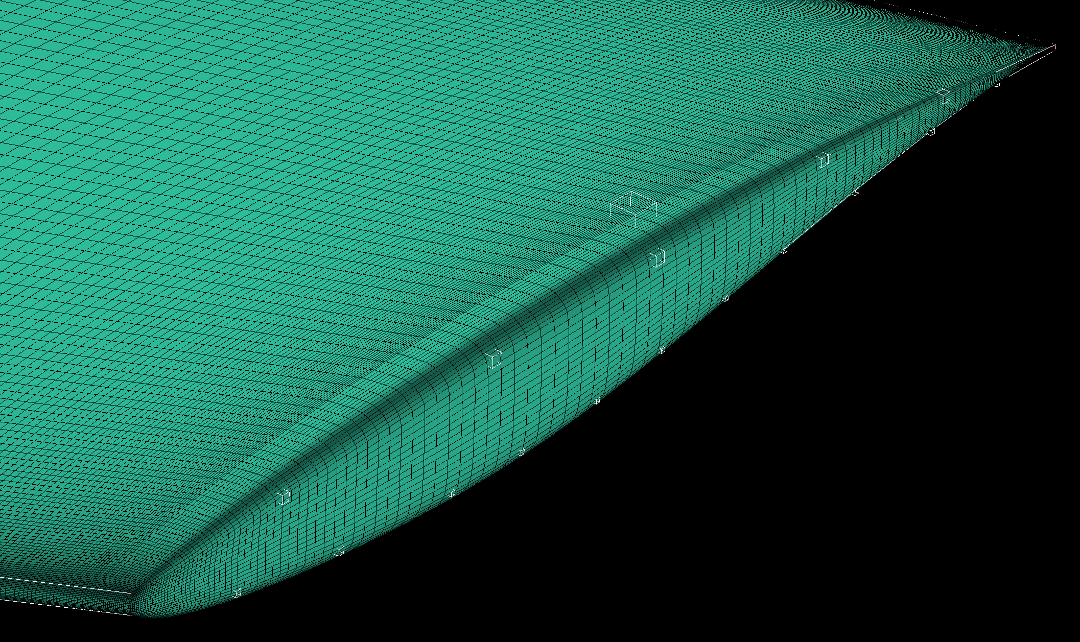
9. Check mesh quality again
Using the mesh quality check, we see that we have a better quality mesh at this point (although it can certainly still be improved with more fine tuning and splitting of edges).
Note
To improve the mesh quality further, the vertical edge of the wing tip at the leading edge can also be disassociated from its curve and associated with a surface instead using
Disassociate from GeometryandAssociate edge to Surfacelike the other edges.
10. Ensure correct block orientation
We now have a pre-mesh defined over the surface of the wing. Before proceeding, we need to check the orientation of the blocking. For pyHyp to correctly extrude the mesh and for the boundary conditions to be applied properly, it is essential that the blocking is correctly oriented. The orientation of the blocking can be checked in the
Edit Block(fourth button under theBlockingtab) menu. Within that menu, select the button withijkandkjiin the icon. That will open theChange Block IJKsub menu, as shown below.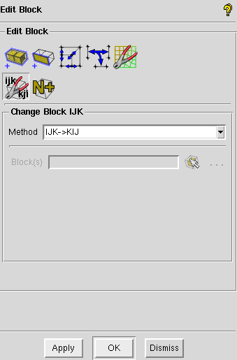
If the blocking faces are not shown, turn them on in the hierarchy tree. When they are enabled and the
Change Block IJKbutton is selected, the faces of the blocking should be red and green. If the blocking is properly oriented, all of the green sides of the faces will be outward facing. If any of the faces have red facing outward, select the icon in theChange Block IJKand select the face to flip.Note
To see the colors of the faces while moving the model, use Dynamic Mode (see Navigating in ICEM).
Convert to MultiBlock Mesh
Converting the pre-mesh to a multiblock mesh is relatively straightforward.
Right-click on Pre-Mesh in the model tree.
In the menu that opens, select Convert to MultiBlock Mesh.
A Mesh branch should then be added to the hierarchy tree.
Export the mesh
Exporting the mesh is done from the Output tab.
The first step is to select the first button, with the red toolbox.
This opens a menu where you can select the solver to export to.
For our purposes, select CGNS.
At that point, the fourth and final button under the Output tab can be selected.
At the prompt, click Open to use your multiblock mesh.
Then select All domains of the mesh.
After that a window should come up with saving options.
All of the default options should work.
The window is shown below.
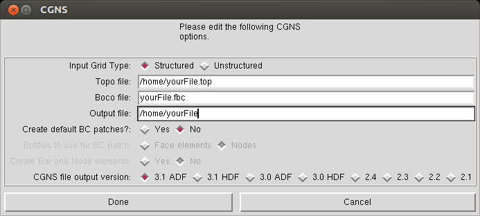
Make sure to name your output file wing_surf_L1.cgns.
The L1 surface mesh is now ready for use in pyHyp.
Warning
The size of the L1 mesh generated in the ICEM version of the tutorial is slightly coarser than the one generated in the Pointwise version of the tutorial. This shouldn’t dramatically impact your results but is something to keep in mind. This discrepancy is primarily because the ICEM version of the tutorial is from an older version of the MACH-Aero tutorial from when ICEM CFD was the meshing software of choice in the MDO Lab
Note
An older version of the MACH-Aero tutorial would now instruct users to coarsen their mesh in ICEM itself by reducing the number of nodes specified for the edges so far from 17 to 5 and 161 to 41.
This step is now obsolete with the introduction of mesh family generation in the mesh extrusion step.
However, the resulting surface and volume meshes, wing.cgns and wing_vol.cgns respectively, from this coarsening operation were included in the tutorial repo for reference or use in the tutorial itself.
As a result, these meshes ended up getting used in various training sessions, examples, classes, and other studies as they were readily available.
These files have now been replaced in this version of the MACH-Aero tutorial and the old files can only be obtained by downloading an older version of the MACH-Aero tutorial from GitHub.